- Posts: 190
- Thank you received: 16
Gear Selector Switch Wiring
- alsancle
-

- Offline
- Moderator
-
Registered
Less
More
20 Sep 2020 13:37 #41009
by alsancle
Replied by alsancle on topic Gear Selector Switch Wiring
Thanks Jim. Feed them one at a time from the bottom?
Please Log in or Create an account to join the conversation.
- JIM.OBRIEN
- Offline
- Premium Forum User
-
Registered
Less
More
- Posts: 586
- Thank you received: 217
20 Sep 2020 01:04 #41002
by JIM.OBRIEN
Replied by JIM.OBRIEN on topic Gear Selector Switch Wiring
AL, You can replace the shift wiring harness with the steering column in the car. I have done two recently. It take a little more work (but not as much as removing the steering column). It helps if you have a second set of hands to help out with feeding the wires thru the column and when soldering the switch. You will have to solder the switch while you are sitting in the car.
The following user(s) said Thank You: 1748 S
Please Log in or Create an account to join the conversation.
- 1748 S
- Away
- Platinum Forum User
-
Registered
Less
More
- Posts: 1749
- Thank you received: 134
19 Sep 2020 00:12 #40987
by 1748 S
Thanks for the information. I'm located about 3 hours south of this. I really want to walk thru the Henry shop just to see what he was doing and look at the tooling. Maybe purchase something I "can't do without"... Tell the wife I just need one more part....
Gary Parsons
Replied by 1748 S on topic Gear Selector Switch Wiring
Rileypu29 wrote: I just purchased two water pump rebuild kits from Cathy Portz who is indeed still selling Henry's parts. There is a website for ordering. Cathy is great to work with and shipped the parts very quickly. I highly recommend buying parts from her.
Bill Kastanis
Thanks for the information. I'm located about 3 hours south of this. I really want to walk thru the Henry shop just to see what he was doing and look at the tooling. Maybe purchase something I "can't do without"... Tell the wife I just need one more part....
Gary Parsons
Please Log in or Create an account to join the conversation.
- Rileypu29
-

- Offline
- Senior Forum User
-
Registered
Less
More
- Posts: 82
- Thank you received: 14
18 Sep 2020 17:07 #40981
by Rileypu29
Bill Kastanis
Replied by Rileypu29 on topic Gear Selector Switch Wiring
I just purchased two water pump rebuild kits from Cathy Portz who is indeed still selling Henry's parts. There is a website for ordering. Cathy is great to work with and shipped the parts very quickly. I highly recommend buying parts from her.
Bill Kastanis
Bill Kastanis
Bill Kastanis
Please Log in or Create an account to join the conversation.
- alsancle
-
- Offline
- Moderator
-
Registered
Less
More
- Posts: 190
- Thank you received: 16
18 Sep 2020 14:05 #40979
by alsancle
Replied by alsancle on topic Gear Selector Switch Wiring
I believe his daughter is selling off his inventory via his website, but since I don't have it in my hands yet, we shall see.
Please Log in or Create an account to join the conversation.
- 1748 S
- Away
- Platinum Forum User
-
Registered
Less
More
- Posts: 1749
- Thank you received: 134
18 Sep 2020 13:53 #40978
by 1748 S
Replied by 1748 S on topic Gear Selector Switch Wiring
How can you have purchased something from Henry Portz? I suspect you purchased the fake plug several years ago. But VERY interested in your response too.
Gary Parsons
Gary Parsons
Please Log in or Create an account to join the conversation.
- alsancle
-
- Offline
- Moderator
-
Registered
Less
More
- Posts: 190
- Thank you received: 16
18 Sep 2020 12:20 #40977
by alsancle
Replied by alsancle on topic Gear Selector Switch Wiring
I ordered the one piece loom from RI wiring. Looks like 8-10 weeks which reminds me I should have been moving quicker earlier in the summer. Also, I ordered the fake plug from Henry Portz.
I told my dad we are taking the steering tube out and he was disagreeing since he didn't have to do it last time, and I pointed out that last time he didn't replace the harness.
I told my dad we are taking the steering tube out and he was disagreeing since he didn't have to do it last time, and I pointed out that last time he didn't replace the harness.
Please Log in or Create an account to join the conversation.
- JIM.OBRIEN
- Offline
- Premium Forum User
-
Registered
Less
More
- Posts: 586
- Thank you received: 217
14 Sep 2020 14:49 #40959
by JIM.OBRIEN
Replied by JIM.OBRIEN on topic Gear Selector Switch Wiring
Terry is correct you have to feed the wires from the bottom of the steering column. You want to sort them out first so when they come out on top they feed directly into the shift arm housing and the switch. I'll post the order of the wires later, all my notes are in the shop.
Originally there was a cardboard "washer" the wires ran thru that was located at the base of the shift arm (at the steering column). Your best bet is to pull in two or three wires at a time. I always use a string to pull in the wires and ALWAYS have a spare pull string in the column.
Originally there was a cardboard "washer" the wires ran thru that was located at the base of the shift arm (at the steering column). Your best bet is to pull in two or three wires at a time. I always use a string to pull in the wires and ALWAYS have a spare pull string in the column.
The following user(s) said Thank You: alsancle
Please Log in or Create an account to join the conversation.
- Terry Cockerell
-
 Topic Author
- Offline
- Elite Forum User
-
Registered
Less
More
- Posts: 1339
- Thank you received: 303
14 Sep 2020 00:31 - 14 Sep 2020 00:32 #40957
by Terry Cockerell
T cockerell
Replied by Terry Cockerell on topic Gear Selector Switch Wiring
NO, the cotton covering of the loom makes it too big to pass through from the top. You have to pass the separate wires up from the bottom.
Make sure you have the inside grommet fitted to the column tube as shown in the attached picture.

Make sure you have the inside grommet fitted to the column tube as shown in the attached picture.
T cockerell
Last edit: 14 Sep 2020 00:32 by Terry Cockerell. Reason: Adding picture
The following user(s) said Thank You: alsancle
Please Log in or Create an account to join the conversation.
- alsancle
-
- Offline
- Moderator
-
Registered
Less
More
- Posts: 190
- Thank you received: 16
13 Sep 2020 13:24 #40948
by alsancle
Replied by alsancle on topic Gear Selector Switch Wiring
Jim, is it possible to feed the harness down from the top? That would allow me to temporarily connect and test the selection switch inside the arm before assembling.
Please Log in or Create an account to join the conversation.
- JIM.OBRIEN
- Offline
- Premium Forum User
-
Registered
Less
More
- Posts: 586
- Thank you received: 217
07 Sep 2020 23:12 #40896
by JIM.OBRIEN
Replied by JIM.OBRIEN on topic Gear Selector Switch Wiring
If you are using the one piece wiring harness(which I highly recommend) you need to feed the wires up from the bottom of the steering column tube. When you feed them up the column lay them out in order they need to go into the shift housing so you don't have the wires twisting up in the shift housing.
Please Log in or Create an account to join the conversation.
- alsancle
-
- Offline
- Moderator
-
Registered
Less
More
- Posts: 190
- Thank you received: 16
07 Sep 2020 11:56 #40886
by alsancle
Replied by alsancle on topic Gear Selector Switch Wiring
Thanks. I was hoping I could use a fish tape to pull the wires back, but from reading your reply it looks like the column tube needs to come out to get the wires back down?
Please Log in or Create an account to join the conversation.
- Terry Cockerell
-
Topic Author
- Offline
- Elite Forum User
-
Registered
Less
More
- Posts: 1339
- Thank you received: 303
07 Sep 2020 08:49 #40885
by Terry Cockerell
T cockerell
Replied by Terry Cockerell on topic Gear Selector Switch Wiring
You can remove the steering column cover tube from the car.
You must first slide the ten wires up through the steering column cover tube and solder the new switch in position. Run your tests with the column out of the car. Eventually when installing the cover tube complete with wiring make sure the inside grommet is in position. Pass the wiring through the firewall then slide the cover tube down the steering column. To refit the engine side grommet you will have to cut it radially as it won't fit over the wires coming out at the bottom of the cover tube. Place the grommet in position and superglue the cut joint. This procedure worked for me.
You must first slide the ten wires up through the steering column cover tube and solder the new switch in position. Run your tests with the column out of the car. Eventually when installing the cover tube complete with wiring make sure the inside grommet is in position. Pass the wiring through the firewall then slide the cover tube down the steering column. To refit the engine side grommet you will have to cut it radially as it won't fit over the wires coming out at the bottom of the cover tube. Place the grommet in position and superglue the cut joint. This procedure worked for me.
T cockerell
The following user(s) said Thank You: alsancle
Please Log in or Create an account to join the conversation.
- alsancle
-
- Offline
- Moderator
-
Registered
Less
More
- Posts: 190
- Thank you received: 16
07 Sep 2020 00:50 #40884
by alsancle
Replied by alsancle on topic Gear Selector Switch Wiring
Thinking about it over the weekend, I think I'm going to get the full length harness, install the new selection switch with the new harness and connect the other end to the interlock and front control without running the harness or installing the column stock. This will allow me to test everything without having to install all the wiring. Once I know it works, then I can disconnect the wires up front, and thread them down the column and pull the rest of the harness through.
Bad idea?
Bad idea?
Please Log in or Create an account to join the conversation.
- alsancle
-
- Offline
- Moderator
-
Registered
Less
More
- Posts: 190
- Thank you received: 16
04 Sep 2020 00:16 - 04 Sep 2020 00:17 #40853
by alsancle
Replied by alsancle on topic Gear Selector Switch Wiring
My dad and I finally got around to removing the wiring harness from the column. The wires look to be 2 million years old. I was going to order the selection switch harness from RI wiring but thought I would ask if there is any consensus on replacing the partial harness with a single one (and fake plug) all the way to the transmission?
The trade-offs I see are:
1. A single harness eliminates any issues with the plug.
2. A single harness eliminates me trying to solder the connections on to the plug
3. A single harness means you can't pull just the selection harness out to work on the switch.
4. A single harness means more work with installing the front 1/2 of the harness.
Final question, if I go with just the selection harness, is anyone making the plug or half the plug?
Last edit: 04 Sep 2020 00:17 by alsancle.
Please Log in or Create an account to join the conversation.
- Terry Cockerell
-
Topic Author
- Offline
- Elite Forum User
-
Registered
Less
More
- Posts: 1339
- Thank you received: 303
27 Jul 2020 21:01 - 27 Jul 2020 21:04 #40611
by Terry Cockerell
T cockerell
Replied by Terry Cockerell on topic Gear Selector Switch Wiring
These simple tools make the job of installing or removing the snap ring quite an easy task. For a full description and list of dimensions check out the Forum heading, Not Sure I Have A Problem.
T cockerell
Last edit: 27 Jul 2020 21:04 by Terry Cockerell. Reason: Revising text
Please Log in or Create an account to join the conversation.
- alsancle
-
- Offline
- Moderator
-
Registered
Less
More
- Posts: 190
- Thank you received: 16
24 Jul 2020 17:01 #40602
by alsancle
Replied by alsancle on topic Gear Selector Switch Wiring
Thanks to all for your input! This thread has some good pictures of tools that might help with what looks like a miserable job.
phpstack-1081784-3880776.cloudwaysapps.c...-if-i-have-a-problem
phpstack-1081784-3880776.cloudwaysapps.c...-if-i-have-a-problem
Please Log in or Create an account to join the conversation.
- rhauser
- Offline
- Senior Forum User
-
Registered
Less
More
- Posts: 54
- Thank you received: 0
24 Jul 2020 16:12 #40600
by rhauser
Replied by rhauser on topic Gear Selector Switch Wiring
Yes there is a snap ring down in the tube on the back side of the switch and it can only go in that way.
Robert l Hauser
Robert l Hauser
Please Log in or Create an account to join the conversation.
- 1748 S
- Away
- Platinum Forum User
-
Registered
Less
More
- Posts: 1749
- Thank you received: 134
24 Jul 2020 14:43 #40599
by 1748 S
Replied by 1748 S on topic Gear Selector Switch Wiring
Thank you so much for the great explanation of doing this job Jim. My switch and housing came from Henry Ports many years ago. It was completely disassembled too so I have no idea how it was installed but... Now I sure do.Is there another improved snap ring we can purchase? If so from who?
Gary Parsons
Gary Parsons
Please Log in or Create an account to join the conversation.
- JIM.OBRIEN
- Offline
- Premium Forum User
-
Registered
Less
More
- Posts: 586
- Thank you received: 217
24 Jul 2020 01:20 #40597
by JIM.OBRIEN
Replied by JIM.OBRIEN on topic Gear Selector Switch Wiring
Hi Al, If you look closely at the housing there is a notch (like a keyway) in the housing . This area allows you to get behind the snap ring and pry it out. If you are lucky the end of the snap ring is near the notch. I use a long thin screwdriver to get behind the snap ring and pry it out of the groove. At the same time I use a O-ring tool or a dental pick to grab the snap ring and pull it out.
If the end of the snap ring is not near the notch try and a use the screwdriver to move it around so it is near the notch.
This is one job I would rather be lucky then good. I have had this job take me as long as 4 hours to get the ring out. I've done it enough lately I can get it out in less then 5 mins.
If you are having problems call me
The following user(s) said Thank You: 1748 S, alsancle
Please Log in or Create an account to join the conversation.
- 1748 S
- Away
- Platinum Forum User
-
Registered
Less
More
- Posts: 1749
- Thank you received: 134
24 Jul 2020 00:35 - 24 Jul 2020 00:38 #40596
by 1748 S
Replied by 1748 S on topic Gear Selector Switch Wiring
nOT ABLE TO SUGGEST A WAY TO REMOVE THE SNAP RING BUT i'M TOLD ITS very DIFFICULT. i BET A SPECIAL TOOL IS GOING TO HAVE TO BE MADE. i NOTICED THE SWITCH APPEARS TO HAVE WLWCTRICAL TAPE WRAPPED AROUND IT. bE SURE TO WRAP THIS AGAIN OR USE SOME SHRINK WRAP IN THE EXPOSED CONDUCTOR AREA. tHEY GET REALLY CLOSE TO THE HOUSING AND A SHORT IS NOT SOMETHING YOU WANT IN THIS AREA.
gARY pARSONS
gARY pARSONS
Last edit: 24 Jul 2020 00:38 by 1748 S. Reason: Sorry for the above post. Wife left computer on caps and I did not notice. I two finger type watching the keyboard
Please Log in or Create an account to join the conversation.
- alsancle
-
- Offline
- Moderator
-
Registered
Less
More
- Posts: 190
- Thank you received: 16
23 Jul 2020 22:42 #40595
by alsancle
Replied by alsancle on topic Gear Selector Switch Wiring
Ok, so examining the snap ring (see picture) I have no idea how to compress that. Any suggestions?
Please Log in or Create an account to join the conversation.
- alsancle
-
- Offline
- Moderator
-
Registered
Less
More
- Posts: 190
- Thank you received: 16
23 Jul 2020 21:01 #40594
by alsancle
Replied by alsancle on topic Gear Selector Switch Wiring
Thank you! Any idea who might have the updated snap rings?
Please Log in or Create an account to join the conversation.
- JIM.OBRIEN
- Offline
- Premium Forum User
-
Registered
Less
More
- Posts: 586
- Thank you received: 217
22 Jul 2020 23:56 #40588
by JIM.OBRIEN
Replied by JIM.OBRIEN on topic Gear Selector Switch Wiring
A couple of points on this thread - Terry, the switch you have there is an aftermarket switch - very different from the original but functions the same.
AJ - the housing has a keyway cut in it and the switch has a square on it so it will only go in one way.
The original snap ring was just a circular piece. This makes it hard to get out. There are updated ones out there that have a ring on the one end that makes it easy to grab and remove the snap ring.
My next article for the Newsletter will be on this subject. Will also include testing the switch to make sure it will work in the car.
The following user(s) said Thank You: 1748 S, alsancle
Please Log in or Create an account to join the conversation.
- uconn_1965
- Offline
- Moderator
-
Registered
Less
More
- Posts: 369
- Thank you received: 97
22 Jul 2020 22:50 #40585
by uconn_1965
Replied by uconn_1965 on topic Gear Selector Switch Wiring
The switch is held in with snap ring. Also the shift body only comes out one way. ( side towards 10 wires)
The following user(s) said Thank You: alsancle
Please Log in or Create an account to join the conversation.
- alsancle
-
- Offline
- Moderator
-
Registered
Less
More
- Posts: 190
- Thank you received: 16
22 Jul 2020 21:02 #40584
by alsancle
Replied by alsancle on topic Gear Selector Switch Wiring
I'm trying to replace bakelite switch with a new switch body made on a 3D printer by Pat Leahy. So, unless I disassemble the column to get the harness out, I will be trying to do what Terry is doing.
I will say that things are pretty tight. My question is probably simple, is there a snap ring holding the switch body inside the shifter housing? And can the body only go in one way?
thanks,
A.J.
I will say that things are pretty tight. My question is probably simple, is there a snap ring holding the switch body inside the shifter housing? And can the body only go in one way?
thanks,
A.J.
Please Log in or Create an account to join the conversation.
- Terry Cockerell
-
Topic Author
- Offline
- Elite Forum User
-
Registered
Less
More
- Posts: 1339
- Thank you received: 303
24 Jun 2020 21:09 #40416
by Terry Cockerell
T cockerell
Replied by Terry Cockerell on topic Gear Selector Switch Wiring
After making sure the soldered connections were all solid and that the cables were in the correct locations fitting the switch cover and internal rotating switch contact was not too bad. I then wrapped some insulation tape around the switch and cables. Literature I had said to use a piece of 3/16" threaded rod long enough to pass through the assembly with washers and nuts either end to compress the internal spring. With this in place fitting the internal circlip is a lot easier. The assemble was then moved towards the tube cover as the cables were pulled at the 10 pin plug end. It all went together pretty smoothly.
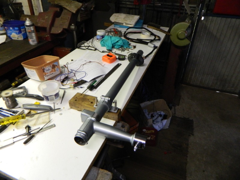
The job could be done with the steering column tube cover in position but it would be more tedious. Having it all out of the car makes it a lot easier to work on as you can rotate the tube cover when soldering the various connections around the switch.
The job could be done with the steering column tube cover in position but it would be more tedious. Having it all out of the car makes it a lot easier to work on as you can rotate the tube cover when soldering the various connections around the switch.
T cockerell
Please Log in or Create an account to join the conversation.
- uconn_1965
- Offline
- Moderator
-
Registered
Less
More
- Posts: 369
- Thank you received: 97
24 Jun 2020 16:29 #40415
by uconn_1965
Replied by uconn_1965 on topic Gear Selector Switch Wiring
Hmmm. Terry I hope you make out OK.. I’ve always wired the Bakelite switch first so I can feed the wires thru the shift arm and install the snap ring and then down the steering column tube. Also originally there is a fiber like cardboard round disk with holes in it that keeps the wires in the correct position at the back of the Bakelite switch.
The following user(s) said Thank You: 1748 S
Please Log in or Create an account to join the conversation.
- alsancle
-
- Offline
- Moderator
-
Registered
Less
More
- Posts: 190
- Thank you received: 16
24 Jun 2020 11:49 - 24 Jun 2020 11:52 #40413
by alsancle
Replied by alsancle on topic Gear Selector Switch Wiring
Terry, thank you for the pictures and write up. I'm wondering how hard this is going to be to do in the car. I'm also trying to convince my dad we should bite the bullet on a one piece harness.
A.J.
A.J.
Last edit: 24 Jun 2020 11:52 by alsancle.
Please Log in or Create an account to join the conversation.
- Terry Cockerell
-
Topic Author
- Offline
- Elite Forum User
-
Registered
Less
More
- Posts: 1339
- Thank you received: 303
24 Jun 2020 10:35 - 24 Jun 2020 10:40 #40412
by Terry Cockerell
T cockerell
Replied by Terry Cockerell on topic Gear Selector Switch Wiring
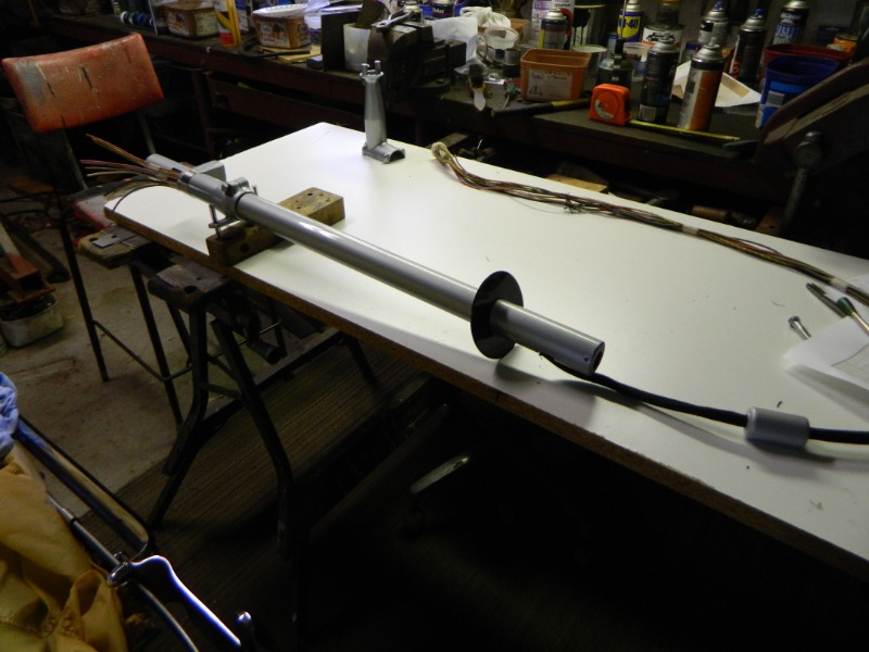
After avoiding the inevitable for long enough I got on with the job of rewiring the gear selector switch with a new one piece wiring loom eliminating the troublesome 10 pin plug.
Laying the cables out correctly is the key to success. The cables have to be slid into the steering column cover tube and pulled through from the bottom up to the switch . I had the cover tube out of the car with the cabin side firewall grommet in position. After carefully removing the old cables and soldering the new ones in position the switch was fitted to the cover tube. Eventually the new loom with a dummy 10 pin plug was fed through the firewall and the cover tube assembly slid down over the steering column and fixed in place. As you cannot slide the firewall side grommet over the cover tube with the cables in place, I simply made a cut through the grommet, positioned it and super glued the joint.
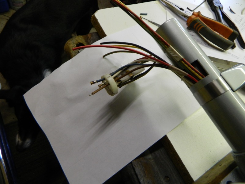
The gear selector switch has some contacts that are a tight fit in the plastic housing. In some reference material it said an ice pick can be used to push the contacts out. I figured pushing a point into soft material may make things worse. I cut the wires off flush with the plastic housing and used a small round flat ended punch to push them out. This worked well.
One day in the not too distant future I hope to be able to change gears again, when the restoration is finished.
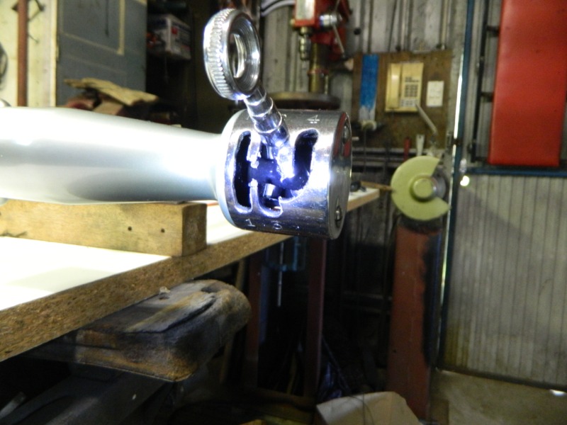
One final note, I painted the insides of the switch gate black as it didn't look right in raw metal colours.
Laying the cables out correctly is the key to success. The cables have to be slid into the steering column cover tube and pulled through from the bottom up to the switch . I had the cover tube out of the car with the cabin side firewall grommet in position. After carefully removing the old cables and soldering the new ones in position the switch was fitted to the cover tube. Eventually the new loom with a dummy 10 pin plug was fed through the firewall and the cover tube assembly slid down over the steering column and fixed in place. As you cannot slide the firewall side grommet over the cover tube with the cables in place, I simply made a cut through the grommet, positioned it and super glued the joint.
The gear selector switch has some contacts that are a tight fit in the plastic housing. In some reference material it said an ice pick can be used to push the contacts out. I figured pushing a point into soft material may make things worse. I cut the wires off flush with the plastic housing and used a small round flat ended punch to push them out. This worked well.
One day in the not too distant future I hope to be able to change gears again, when the restoration is finished.
One final note, I painted the insides of the switch gate black as it didn't look right in raw metal colours.
T cockerell
Last edit: 24 Jun 2020 10:40 by Terry Cockerell. Reason: Adding pictures
Please Log in or Create an account to join the conversation.
- mikespeed35
-

- Offline
- ACD Club Life Member
-
Registered
Less
More
- Posts: 886
- Thank you received: 194
15 May 2020 04:12 #40177
by mikespeed35
Mike Huffman
Replied by mikespeed35 on topic Gear Selector Switch Wiring
Shrink tubing can be used for other applications that don't involve wiring. It comes in many diameters.
CORDiallyMike
CORDiallyMike
Mike Huffman
Please Log in or Create an account to join the conversation.
- alsancle
-
- Offline
- Moderator
-
Registered
Less
More
- Posts: 190
- Thank you received: 16
14 May 2020 13:37 #40171
by alsancle
Replied by alsancle on topic Gear Selector Switch Wiring
Please Log in or Create an account to join the conversation.
- STEVEN.KUIPER
- Offline
- Senior Forum User
-
Registered
Less
More
- Posts: 91
- Thank you received: 17
14 May 2020 13:02 #40170
by STEVEN.KUIPER
Replied by STEVEN.KUIPER on topic Gear Selector Switch Wiring
for covering soldier connections there is a product called "heat shrink" which is much less noticeable and smaller in diameter than the connector shown on the 1st page here.
essentially a rubber-like black tube(colors are available) that you slide back one of the wires before you soldier them. after soldiering is done slide it over the joint & heat lightly . then it shrinks down to size.
essentially a rubber-like black tube(colors are available) that you slide back one of the wires before you soldier them. after soldiering is done slide it over the joint & heat lightly . then it shrinks down to size.
Please Log in or Create an account to join the conversation.
- JIM.OBRIEN
- Offline
- Premium Forum User
-
Registered
Less
More
- Posts: 586
- Thank you received: 217
13 May 2020 21:15 #40168
by JIM.OBRIEN
Replied by JIM.OBRIEN on topic Gear Selector Switch Wiring
Gary - The drawing you posted is a repop Stan was selling. The drawing Wynn posted By Henry and Jim Howell is the original.
Please Log in or Create an account to join the conversation.
- wynlaidig
- Offline
- ACD Club Life Member
-
Registered
Less
More
- Posts: 259
- Thank you received: 44
12 May 2020 22:34 #40164
by wynlaidig
Replied by wynlaidig on topic Gear Selector Switch Wiring
JKH drew up the wire guard that fits into the selector arm behind the switch to keep the wires in order. The originals were thin bakelite and often broke. But they should be easy to make, and keep the wires aligned inside the arm. He didn't specify the diameter. I think I have a broken one somewhere that I can measure if need be. See attached file.
Please Log in or Create an account to join the conversation.
- 1748 S
- Away
- Platinum Forum User
-
Registered
Less
More
- Posts: 1749
- Thank you received: 134
12 May 2020 21:29 #40161
by 1748 S
Jim are you telling us this switch is a repop or the diagram is a repop? I had to ask to be clear. I'm not understanding what you are referencing the repop to...I will have to look at my original switch to see if I can determine the differences.
Gary Parsons
Replied by 1748 S on topic Gear Selector Switch Wiring
JIM.OBRIEN wrote: That's a repop not an original.
Jim are you telling us this switch is a repop or the diagram is a repop? I had to ask to be clear. I'm not understanding what you are referencing the repop to...I will have to look at my original switch to see if I can determine the differences.
Gary Parsons
Please Log in or Create an account to join the conversation.
- johnmereness
- Offline
- Moderator
-
Registered
Less
More
- Posts: 767
- Thank you received: 159
12 May 2020 17:08 #40157
by johnmereness
JMM
Replied by johnmereness on topic Gear Selector Switch Wiring
Yes, Pat Leahy - and he actually drives his cars too
JMM
Please Log in or Create an account to join the conversation.
- JIM.OBRIEN
- Offline
- Premium Forum User
-
Registered
Less
More
- Posts: 586
- Thank you received: 217
12 May 2020 12:19 #40155
by JIM.OBRIEN
Replied by JIM.OBRIEN on topic Gear Selector Switch Wiring
That's a repop not an original.
Please Log in or Create an account to join the conversation.
- 1748 S
- Away
- Platinum Forum User
-
Registered
Less
More
- Posts: 1749
- Thank you received: 134
12 May 2020 02:57 #40153
by 1748 S
Replied by 1748 S on topic Gear Selector Switch Wiring
I found this in my files today. Its surprising how these selector switches are made. Enjoy.
The following user(s) said Thank You: alsancle
Please Log in or Create an account to join the conversation.
- alsancle
-
- Offline
- Moderator
-
Registered
Less
More
- Posts: 190
- Thank you received: 16
10 May 2020 15:34 #40141
by alsancle
Replied by alsancle on topic Gear Selector Switch Wiring
Thanks. I saw that and sent him a PM yesterday. I'll buy one regardless. It looks like our car already has a non original replacement of some sort.JIM.OBRIEN wrote: If the problem is the interlock switch on the cross shift change it out to a modern micro switches. They are a lot easier to set up. Pat Leahy has them.
Please Log in or Create an account to join the conversation.
- JIM.OBRIEN
- Offline
- Premium Forum User
-
Registered
Less
More
- Posts: 586
- Thank you received: 217
10 May 2020 15:15 #40140
by JIM.OBRIEN
Replied by JIM.OBRIEN on topic Gear Selector Switch Wiring
If the problem is the interlock switch on the cross shift change it out to a modern micro switches. They are a lot easier to set up. Pat Leahy has them.
Please Log in or Create an account to join the conversation.
- alsancle
-
- Offline
- Moderator
-
Registered
Less
More
- Posts: 190
- Thank you received: 16
09 May 2020 21:56 #40136
by alsancle
Replied by alsancle on topic Gear Selector Switch Wiring
Is anybody making a new improved selector switch? I'm working with my dad tracing his shifting problems, and the issue is electrical in either the interlock or the selector switch. Would like to have a new one in my hands before we take it apart.
Please Log in or Create an account to join the conversation.
- johnmereness
- Offline
- Moderator
-
Registered
Less
More
- Posts: 767
- Thank you received: 159
01 Dec 2018 21:06 #36051
by johnmereness
JMM
Replied by johnmereness on topic Gear Selector Switch Wiring
As a sidnote - I have successfully repaired a few pieces of Bakelite with 3M panel adhesive that they use to "weld" replacement sheet metal panels onto new cars - you just need a clean mating surface and plenty time and patience. - my point being try your best and if something goes wrong do not give up hope. Also, I have at times stripped the woven coating off of certain places in light connectors and --- you still have the PVC coating to protect and that extra space is a real blessing at times.
JMM
The following user(s) said Thank You: 1748 S
Please Log in or Create an account to join the conversation.
- 1748 S
- Away
- Platinum Forum User
-
Registered
Less
More
- Posts: 1749
- Thank you received: 134
29 Nov 2018 22:28 #36038
by 1748 S
Replied by 1748 S on topic Gear Selector Switch Wiring
Yes, at this time I plan on using this because I see no issues like we'll worn contacts. Replacing all these pieces will cost just over a thousand U S. I know this part is probably 80 plus years old but. For about 40 of that has been in a plastic bag out of the shop. Kind of in my Cord parts vault.
Please Log in or Create an account to join the conversation.
- Terry Cockerell
-
Topic Author
- Offline
- Elite Forum User
-
Registered
Less
More
- Posts: 1339
- Thank you received: 303
29 Nov 2018 21:20 #36037
by Terry Cockerell
T cockerell
Replied by Terry Cockerell on topic Gear Selector Switch Wiring
Gary Bakelite would have been the ideal material back then but as you said very fragile.
Are you intending on using this original switch?
Are you intending on using this original switch?
T cockerell
Please Log in or Create an account to join the conversation.
- 1748 S
- Away
- Platinum Forum User
-
Registered
Less
More
- Posts: 1749
- Thank you received: 134
29 Nov 2018 15:43 #36036
by 1748 S
Replied by 1748 S on topic Gear Selector Switch Wiring
Terry here are the pics of my original shift selector switch and associated parts.
Please Log in or Create an account to join the conversation.
- Terry Cockerell
-
Topic Author
- Offline
- Elite Forum User
-
Registered
Less
More
- Posts: 1339
- Thank you received: 303
29 Nov 2018 08:58 - 29 Nov 2018 09:11 #36034
by Terry Cockerell
T cockerell
Replied by Terry Cockerell on topic Gear Selector Switch Wiring
Hi Jim and Gary.
Thanks for your supportive comments. It is a hell of a job restoring a Cord from the ground up after you have taken it all apart. As the gear change mechanism worked so well after sorting out the initial bugs I didn't want to get into more trouble with the switch as I still have a long way to go with everything else. The car is coming along nicely. It must have looked like a space ship in 1936 with its original Cadet grey paint shining in the daylight.
My loom is in one piece so I will take your advice Jim and feed it up through the steering column outer tube before doing any soldering up.
One step at a time.
The last picture shows the Connersville City Flag which the Mayor of Connersville gave me during the Mini Meet we had there before Auburn.
Cheers,
Terry
T cockerell
Last edit: 29 Nov 2018 09:11 by Terry Cockerell. Reason: Revise text
Please Log in or Create an account to join the conversation.
- 1748 S
- Away
- Platinum Forum User
-
Registered
Less
More
- Posts: 1749
- Thank you received: 134
29 Nov 2018 04:05 #36033
by 1748 S
Replied by 1748 S on topic Gear Selector Switch Wiring
Terry... Tomorrow I will take pics and post them of my original shift electrical parts. Henry Portz sold them to me probably 35 plus years ago.He told me NOT you try to take apart the switch because I would break the Bakelite where the snap ring fits.Well it was so long ago when I opened this up I do not recall breaking anything. I probably made a tool at work because I had millions of dollars worth of tools and equipment avail for personal use anytime. It was great using all those tools and machinery for personal use. I so miss that too... Your switch might be made from Delrin plastic. I was just looking in Stan's catalog and that's what he sells. Found on page 57. Part number is 6017 (B10762... Price in 2013 was $658.50 ea.
Please Log in or Create an account to join the conversation.
- JIM.OBRIEN
- Offline
- Premium Forum User
-
Registered
Less
More
- Posts: 586
- Thank you received: 217
29 Nov 2018 03:26 #36032
by JIM.OBRIEN
Replied by JIM.OBRIEN on topic Gear Selector Switch Wiring
Hi Terry,
Gary is right, this is a "newer" switch. Your wires look like they are in good condition and appear to be modern plastic insulated wires with the cloth over them. That's a good point for leaving the wires in place. However if your splices are located in the steering column tube you probably won't get all the wires back in there. It's hard enough to get all the wires in there.
Soldering in the new wires is not too difficult. With this piece you do have to watch the temperature because you can melt the plastic. It makes the job a lot easier if you lay out the wires in the steering column in the same layout of where they need to go in the switch. That way the wires come straight out of the column and go straight into their proper location on the switch - just like it's shown in your photos.
If you have a new one piece harness you have to feed the wires into the column from the bottom and then solder on the switch. This is where you have to feed them into the column in the proper order. If you have the two piece harness you can solder the switch on first, then feed the wires down the steering column and then solder on the connecting plug after the wires are in place.
Personally I would solder the wires onto the switch and not put splices in the wires. The splices are just one more potential problem area.
Good luck with it!
Jim
Please Log in or Create an account to join the conversation.
- Terry Cockerell
-
Topic Author
- Offline
- Elite Forum User
-
Registered
Less
More
- Posts: 1339
- Thank you received: 303
29 Nov 2018 02:24 #36031
by Terry Cockerell
T cockerell
Replied by Terry Cockerell on topic Gear Selector Switch Wiring
Gary that is interesting as I assumed it was an original switch. I guess that switch is not so old.
I think I will splice the cables lower down. It will be safer that way.
I think I will splice the cables lower down. It will be safer that way.
T cockerell
Please Log in or Create an account to join the conversation.